Let’s start
PLC programming with Arduino
by ladder logic diagram.
A Programmable Logic Controller (PLC) is one of computers and used widely to control automatically devices in factories. In controlling the devices by the computers, they generally need some programs written in any programming language such as C, Java, etc., and also need special hardware which can communicate with the devices.
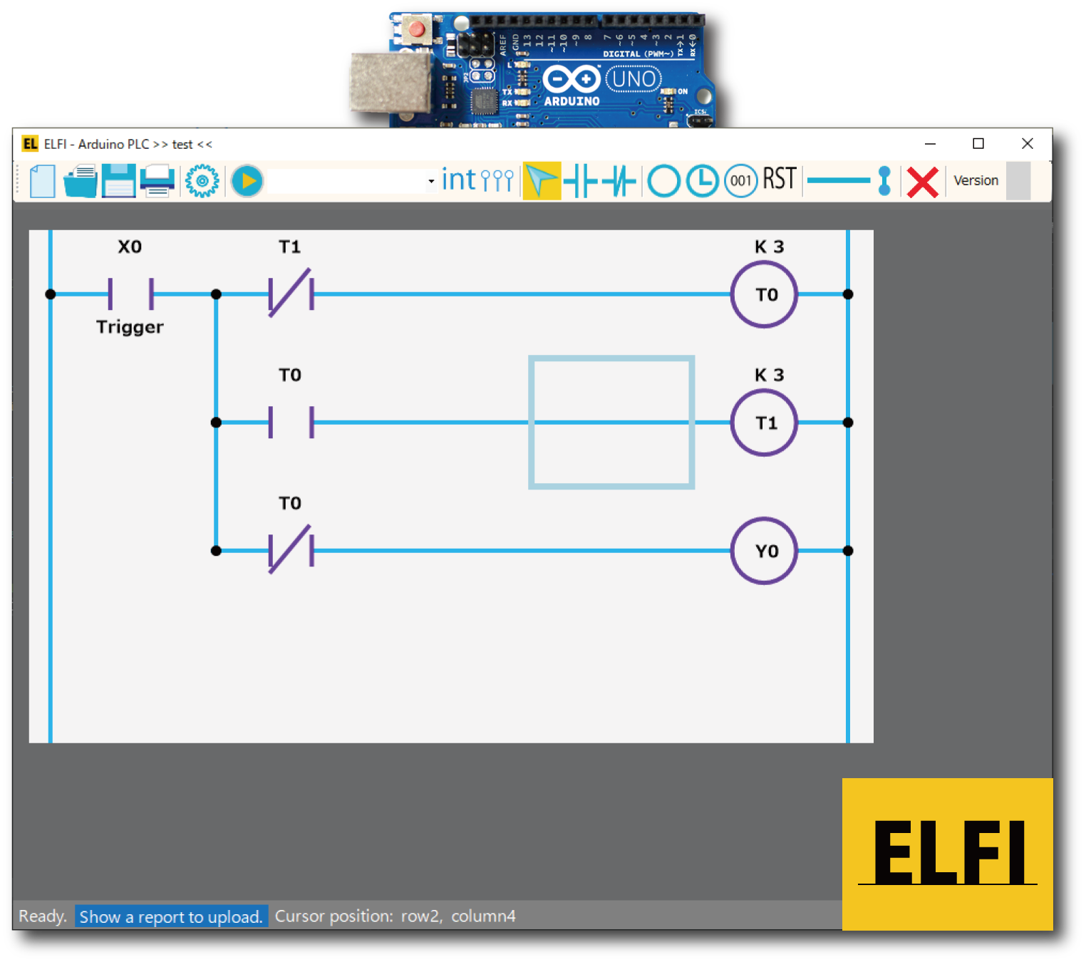
Therefore the PLC also has the special hardware, and however, the programs are often given by drawing a diagram that expresses a flow of electricity. The diagram is called a ladder logic diagram, and here, PLC programming means that we make the diagram for controlling the devices.
To start learning PLC programming, we should prepare a PLC. The ELFI is computer software to program an Arduino as the PLC by only a ladder logic diagram without any program language skills. Therefore, we can concentrate for learning how to program the PLC by the diargram.
Features
ELFI has the below features:
- Supporting 6 components: A switches, B switches, Outputs, Relays, Counters, and Resets.
- Commenting any Elements in a ladder logic diagram.
- Printing and saving a ladder logic diagram as a picture.
- Giving a source code written in Arduino language, which equals to an inputted ladder logic diagram.
- A debug mode can provide the feature that ELFI shows I/O status of the PLC.
- Simulating a ladder logic diagram on PC can be performed (1.0.9.7 Beta 6).
How to Start
Let’s start using ELFI.
Hardware
Please prepare the below hardware:
- An Arduino Uno R3 [Official price: $23]
- A USB Cable (type B) [up to $10]
- An I/O board [if you make it by yourself, up to $10 ]
If you use Tinkercad by Autodesk, you don’t need to prepare the actual above hardware. That’s mean you can start learning PLC programming without any charge because Tinkercad simulates the above hardware on your PC.
Software
Please install the below software and configure ELFI for use.
ELFI recommends "Windows Installer, for Windows 7 and up" if you use Windows PC.
- Launch Arduino IDE
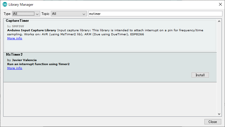
- Go to [Tools]->[Manage Libraries...]
- Type "mstimer" to the left text box (see the below image) and hit the "Enter" key
- Install MsTimer2 by clicking the "Install" button (see the below image)

(MIT License)
[Beta Version 6]
ELFI_1097_Beta6.zip (11315 ダウンロード )
Simulation and Debug of your ladder diagram on PC can be performed.
Beta Version 5
ELFI_1097_Beta5.zip (10536 ダウンロード )
- Only starting X, Y, and M as a component name are accepted.
- Improving Debug Function
(Performance and Showing Conducted Wire). - Choosing the following Arduino boards as PLC:
(Arduino Uno, Arduino Nano, Arduino Nano [Old bootloader]. A board can be chosen at a configuration. ) - Run Button Support
(PLC does not run until digital 12th pin becomes HIGH logic. This function can be enabled at a configuration.) - Improving Compile Error Notification
(Only one output/relay/reset/counter/timer in a line.) - Preventing invalid switch placement
(A/B switch can't be put after an/a output/relay/reset/counter/timer in a line.) - "Save As" button is placed on the toolbar
- Supporting Undo/Redo functions
- Supporting internal pull-up function of Arduino (Please give a check to [Directly connect to switch] to use this in component property. This function should be enabled if your switch doesn't have pull-up/down resistor.)
- Bug fixes of the previous released version.
- Launch the ELFI
- Open Toolbar by clicking the icon
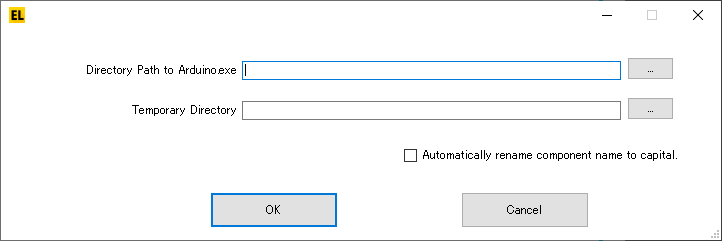
- Set up the below two configurations:
- Directory Path to Arduino.exe: choose a directory that includes Arduino.exe by clicking "..." button.
- Temporary Directory: ELFI uses this directory for communicating with Arduino IDE. A new directory with a simple file path should be created.

https://www.microsoft.com/en-US/download/details.aspx?id=24872
How to Use ELFI
Please replace "at" to @.
It may take long time until I reply your email.