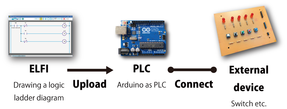
We introduce how to start PLC programming with ELFI. In a PLC programming, generally, we draw our logic ladder diagram and upload to a PLC and connect the PLC to an external device what you want to control. Finally, we check whether the device works fine or not. The difference between a general PLC programming and PLC programming with ELFI is the only using Arduino as PLC.
Toolbar on ELFI
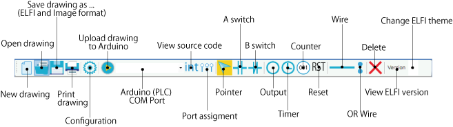
Here we show an overview of the toolbar on ELFI. If you want to put components such as A/B switches, Outputs, Timers, Resets etc. on your diagram, you only click these buttons on the toolbar. These buttons support keyboard shortcuts, and therefore, for example, if you want to put an A switch, you hit ‘a’ key instead of clicking the toolbar button. The other keyboard shortcuts can be found by a tool tip that you move a mouse cursor on components. For example, the tool tip states “A switch (A)” means that this keyboard shortcut is ‘a’ key.

Starting PLC Programming
1. Drawing Logic Ladder Diagram
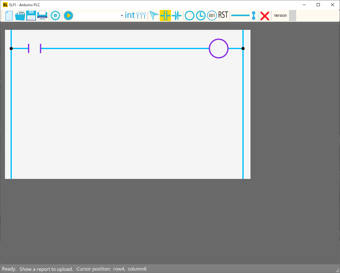
Let’s draw the below diagram with A switch, Output, and Wires.
This diagram states that while the A switch is ON, the Output will generate ON signal.
Now we give unique names to each component. Please click a right button on your mouse and select “Component property” on a menu.
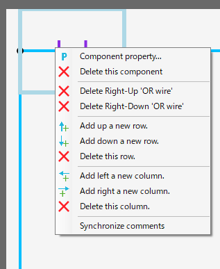
You will see the below window. This window also can be shown by double clicking on component when you are pointer mode or you are just put a component.
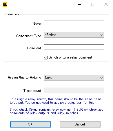
We set that “Name” of the A switch is X0 and “Name” of the Output is Y0 respectively. By clicking “OK” button, you will see the below diagram.
2. Port Assignment
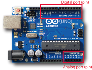
We assign the components on our diagram to actual Arduino PLC ports (pins). We call this “Port (Pin) Assignment “. On Arduino Uno Rev 3, digital ports (pins) from 0 to 13 and analog ports (pins) from A0 to A5 can be used for “Port (Pin) Assignment”. We connect these assigned ports (pins) to external devices such as a mechanical switch (for input) and LED (for output), etc..
We click  “Port (Pin) Assigment” on toolbar to assign
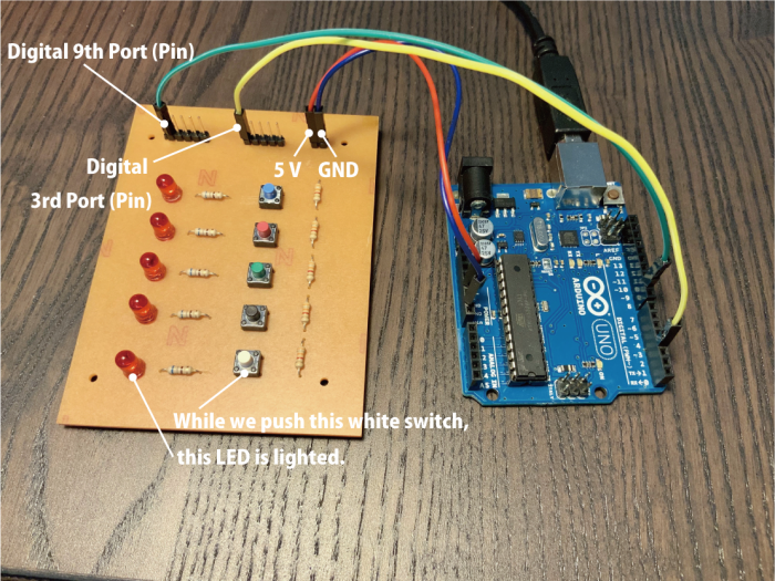
A switch to Digital 3rd port (pin) and Output to Digital 9th port (pin) on the Arduino PLC.
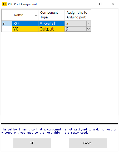
In the next section, we will connect a tact switch to the 3rd port and connect LED to the 9th port. While we push the tact switch, the LED will be lighted.
You shouldn’t use digital 0 pin, because it doesn’t work well.
3. Uploading our Logic Ladder Diagram to PLC (Arduino)
- Connect a PLC (Arduino) to your PC
- Click the
 on toolbar
 - Choose a correct COM port of the PLC (Arduino)
- COM1 may be NOT correct COM port of the PLC (Arduino)
- If here is empty, please wait a moment, and start again at 2nd step.
- Click
 on toolbar and wait a moment. If our logic ladder diagram is fine, and the uploading is over, then you will see “Ready” on a statusbar in the bottom of ELFI window.
- If “Show a report to upload” is blue, we can see a detail report of uploading. This report shows whether the uploading is over correctly or not.

4. Connecting External Device to PLC (Arduino)
We should disconnect the PLC (Arduino) from our PC, before we start connecting any external devices to the PLC (Arduino). This is because if we make a wrong connection such as short, the PLC (Arduino) may be broken and our PC may be broken too. We note that if the PLC (Arduino) is disconnected, it keeps on remembering the program.
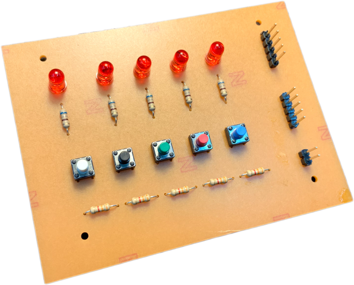
We connect this I/O board to the PLC as the following image. Any boards which include switches and LEDs can be used. However the switches that if the switches are ON, it generate 5 V, and if they are OFF, they generate 0 V are needed. The LEDs that can be accepted for 5 V input are needed too. This is because our PLC, the Arduino UNO , has 5 V system that recognizes 5 V input as the logic level HIGH (1) and 0 V input as the logic level LOW (0) . Our PLC can accept up to 5 V and output up to 5 V & 40 mA too.
5. Verifying our system
We re-connect the PLC (Arduino) to PC. While we push the white switch, LED will be lighted. Does your system work fine? This is end of our introduction.